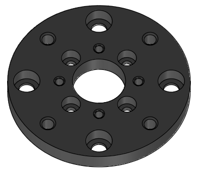
This type of Load Cell is composed of a singular part, which makes it easier to use. Inside this Load Cell are two piezo sensors, one measuring Fz and the other measuring Fx.
In this example of standard assembly, you can see on the front side of the 200N load cell a sticker which is the calibration unit of each axis force, fz and fx, necessary to read correct value based on those reference value.
The 100N suspension assembled on it is used to limit the vibration induced by the sample during testing. There are several variations of suspensions depending on the maximum load it can be effective on.
This type of load cell can be used to perform several types of testing:
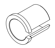
It is recommended to use the brass slit sleeve as it will transfer lateral forces better than the PEEK version.
Rtec Part number: MM000141-02.
Phillips screwdriver
You must use a non-metallic ball holder to avoid influencing the corrosion measurement.
0.125” (3mm) balls:
Holder Material
Rtec Part Number:
PEEK
AM000177-03
0.156” (4mm) balls:
Holder Material
Rtec Part Number:
PEEK
AM000178-03
0.25” (6mm) balls:
Holder Material
Rtec Part Number:
PEEK
AM000091-03
Pin/Ball holder Preparation {{! block}}
Universal Ball holder Overview
Rtec balls catalog
Available Ball materials
E52100 Alloy Steel / HRC60
304 SSt / HRC25
440C SSt / HRC58
WC Tungsten Carbide / HRC75
SiN Silicon Nitride
Nonporous Alumina Ceramic balls
PTFE
Available Ball size
1.6mm
3.9mm
6.3mm
9.5mm
12.7mm
Rtec pins catalog
Available Pin materials
416 SSt
316 SSt
Titanium
Brass
PTFE
Peek
6061 Aluminum
Available Ball size
6.3mm
1. Test Ball or Pin
Provided for standard test: Ball, .250" (1/4") (6.350mm) Dia E52100 100Cr6 grade 25 Alloy Steel.
2. Nut
3. ER11 Collet
General metric range avalaible: from 1 mm to 7 mm (0.5 mm increments)
Each collet has a clamping range of 0.5 mm ex: an ER11-3 mm collet can also clamp pins/balls with a 2.5-3.5 mm diameter.
4. Adjusting pin
This pin enables ball position adjustment within the collet.
5. Ball Holder
Holder Specification
Rtec Part Number: AM000013-01
Collet Series
ER11
Shank Diameter
0.625 in / 15.875 mm
Minimum Collet Capacity
0.0190 in / 0.4826 mm
Maximum Collet Capacity
0.2760 in / 7.0104 mm
Overall Length
3.5 in / 76.2 mm
6. Extension
Left-Hand (reverse) threaded extension.
For additional information or to place an order, please contact Rtec Support (contact information provided at the end of this manual).
Loosen the nut to free the ball.
Remove the adjusting pin from the holder
{{! corr}}
Insert the adjusting pin into the holder, then the ball. Provided for standard test: Ball, .250" (1/4") (6.350mm) Dia E52100 100Cr6 grade 25 Alloy Steel.
Hold the holder vertically, so the ball is resting on the pin. Using a 1/8" Allen key, fasten the screw inside the holder to slightly push the ball.
Once the ball is retracted enough, fasten the nut to secure it.
{{if elec}}
Connect the ring/fork terminal to the brass collar using BHSCS 6-32 X .250” screws and a 7/64" allen key.
Connect the banana cable to the banana plug of the instrument:
Electrical Resistance Measurement (Keithley):
2-Wire measurement
Connect one cable from the collar to the “Force HI” connector.
4-Wire measruement
Connect one cable from the collar to the “Force HI” connector and one cable to “Sense HI”.
Place the collar on the ball holder and strongly tighten the 2 set screws on the side to secure the collet onto the ball holder.
{{If corr}}
Slide the ball holder shaft into the universal ball holder clamp and tighten the nut of the universal ball holder.
For preliminary testing: The ball may be reused by rotating it to expose a unworn contact surface. For final measurements: It is replace the ball between each test.
{{! dry&corr}}
Install the extension on the holder by rotating it counter-clockwise.
Increasing the ball holder length can negatively affect test results (longer force momentum), especially in reciprocating tests. It should only be used when using a chamber
Firstly ,loosen the 2 tightening screws using /16” Allen key.
Slide in the block sample into the block support
Level the block sufficiently into the holder.
Tighten the securing screws on each side.
The self-leveling block holder will ensure proper contact during the test.
Block sample Quotation
Rtec Test Block Size: 0.620 x 0.250 x 0.4
L x l x h in inches
Reference : MM000128-XX
Dimension in inches
Holder Installation
You can either mount the ball holder directly to the load cell or to a suspension which is used to limit the vibration induced by the sample during testing.
A test without suspension will be more noisy but will have a direct transfer of the forces to the load cell.
With a suspension
It is recommended to select a suspension system with the closest higher load rating to the expected load.
Example
For a test at 30N, you would need to use the 50N suspension. By doing so, you will mitigate the vibrations the most.
If you work at 48N it would be better to use a 100N suspension as the 50N suspension would not work for vibrations above 2N.
The labeled force represents the suspension capability, not the nominal operating force. The suspension must be used within this specified range and exceeding this limit will lead to ineffective suspension operation.
Mount the suspension on the graphite plate by tightening the 2 captive screws using 9/64” Allen key.
The label of the suspension should face the same direction as the load cell sticker.
Place the DELRIN disk {{if block&elec}}
Use four 1/4” button head screws to secure the mounting clamp to the load cell suspension and tighten using a 5/32” Allen wrench.
Slide the collet through the clamp {{if ball}}
Without a suspension
Place the DELRIN disk {{! block&elec}}
Use four 1/4” button head screws to secure the assembly to the load cell and tighten using a 5/32” Allen wrench.
Slide the collet through the clamp {{if ball}}
{{! block}}
Insert the slit sleeve into the mounting clamp.
PEEK or Brass slit sleeve, as mentioned in Required tools and components.
Place the ball holder into the slip sleeve.
⚠️
It is recommended to install the holder as far as possible into the suspension while making sure that it does not hit the load cell when the suspension is fully compressed.
{{! ball}}
Align the block holder key with the mounting clamp hole.
Place the block holder into the mounting clamp.
⚠️
It is recommended to install the holder as far as possible into the suspension while making sure that it does not hit the load cell when the suspension is fully compressed.
Tighten the mounting clamp using a 9/64” Allen wrench.
You must use a DELRIN insulator disk to insulate the load cell from the electrified ball holder.
Rtec Part number: MM000668-03
Round mounting clamp
Rtec Part number: MM002514-00
Optional: Quick connection hub (visible in the image above)
Rtec Part number: AM005060-01
Installation
Connect the ring/fork terminal to the brass collar using BHSCS 6-32 X .250” screws and a 7/64" allen key.
Connect the banana cable to the banana plug of the instrument:
Electrical Resistance Measurement (Keithley):
2-Wire measurement
Connect one cable from the collar to the “Force HI” connector.
4-Wire measruement
Connect one cable from the collar to the “Force HI” connector and one cable to “Sense HI”.
Place the collet on the ball holder and strongly tighten the 2 set screws on the side to secure the collet onto the ball holder.
{{if scratch}}
Indentation Application
{{if indent}}
Fast-Exchange Installation
Mounting it with Extension
You can use an extension block to reduce the distance between the load cell and the lower setup.
2" (left) and 4" extensions (right)
Mount the block extension on the exchange plate with 4 4 x 10-32 x 1.250” long screws using 5/32 Allen wrench.
Then the adaptor plate mounted on the extension block with 4 x 10-32 x .625” long screws using 5/32 Allen wrench.
Install the load cell on the fast-exchange attachment by fastening the 4 captive screws using a 5/32" Allen wrench.
The narrow side of the fast exchange plate’s should point to the left of the front load cell as this side will fit into the back of the sliding support.
The front of the load cell is the face showing the Rtec logo and the unit calibration sticker.
{{if mft2&dry}}
Without Extension
Install the load cell on the fast-exchange attachment by fastening the 4 captive screws using a 5/32" Allen wrench.
The narrow side of the fast exchange plate’s should point to the left of the front load cell as this side will fit into the back of the sliding support.
The front of the load cell is the face showing the Rtec logo and the unit calibration sticker.
{{if mft2&!dry}}
Mounting it with Extension
(Optional) You can also use an extension block to reduce the distance between the load cell and the lower setup.
2" (left) and 4" extensions (right)
Without extension block (left) and with extension block (right)
Mount the block extension on the exchange plate with 4 4 x 10-32 x 1.250” long screws using 5/32 Allen wrench.
Then the adaptor plate mounted on the extension block with 4 x 10-32 x .625” long screws using 5/32 Allen wrench.
{{if mft5&dry}}
Without Extension
In most cases, the Argon adapter plate will already be installed. However, if installation is required, follow these steps:
Mount the adaptor plate plate directly to the Quick Exchange base using the provided 4 x 10-32 x 1.250” long screws using 5/32” Allen wrench.
Install the load cell on the fast-exchange attachment by fastening the 4 captive screws using a 5/32" Allen wrench.
Align the sensor so that the ribbon cable port is on the right-hand side when viewed from the front.
This ensures correct orientation in relation to the rear alignment features of the Quick Exchange.
{{if mft5&!dry}}
Installing the Load Cell
Sliding It into the Tester
Slide in the load cell into the Z stage rack.
Make sure the 4 screws above the rack are removed. Slide the load cell with its front facing you and the connector on the right.
Fasten the 4 securing screws by hands.
Connect the ribbon cable. The connector only fit one way.
{{if mft2}}
Manually adjust the Y Radius
To adjust the y radius you need to manually turn the knob to the desired radius.
The center of the Y radius setup being the 25mm mark, you can adjust the radius to +-25mm.
{{if mft2&nxy}}
Sliding It into the Tester
Lower the Z-Axis all the way down using the jogbox.
To create clearance, move the Y-stage.
Before installing the load cell
Lower the Z-Axis all the way down using the jogbox, to have access to the attachement.
Ensure the Y-stage is moved sufficiently backward to avoid obstruction. Although unlikely to cause damage, improper placement may interfere with installation.
Animated instructions
Slide the sensor assembly with the Quick Exchange into the MFT-5000 Quick Exchange Dock
Ensure first that the locking wings are forward.
The front of the load cell (Rtec logo and sticker) is facing you.
Lift the Argon Assembly up while tightening the Quick Exchange locks outward
Always hold the sensor by its sides to avoid applying force on the sensors.
Make sure the assembly is firmly wedged up with no vertical play.
Connect the ribbon cable to the Argon Load Sensor.
The connector only fit one way.
{{if mft5}}
In the next part {{if none}}
Reciprocating Application
{{if reci,stat}}
This application applies to reciprocating motion using both the reciprocating module or the X-axis reciprocating motion (with stationary table).


(6).gif)
(4).gif)
(5).gif)


.gif)
.gif)
.gif)


(1).gif)
 Made with Bullet