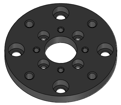
This type of Load Cell is composed of a singular part, which makes it easier to use. Inside this Load Cell are two piezo sensors, one measuring Fz and the other measuring Fx.
In this example of standard assembly, you can see on the front side of the 200N load cell a sticker which is the calibration unit of each axis force, fz and fx, necessary to read correct value based on those reference value.
The 100N suspension assembled on it is used to limit the vibration induced by the sample during testing. There are several variations of suspensions depending on the maximum load it can be effective on.
This type of load cell can be used to perform several types of testing:
The one dimension load cell allows for decoupling for friction and down force sensor.
1D or one dimension Z force/load cell is used to measure down load during the test. The load cell is mounted directly on the Z assembly or on the fast exchange mounting blocks.
The friction arm allows for higher system rigidity and higher friction accuracy measurement at higher load.The sensors comes with two technology, strain gauge based and piezo sensors. Piezo sensors are recommended for applications that requires high frequency response and works only for reciprocating tests.
Load cells are tested and calibrated across wide temperature and humidity ranges. Data is close-looped with the Z motor. The Z load cell contains an amplifier board with friction sensor input and communicates via ethernet cable. Standard ranges and accuracies are listed below. Designed and manufactured at our San Jose facility.
Custom ranges available on request. Applications –High load tests using various modules.
This type of Load Cell is composed of 2 different parts, each one responsible for one axis of force.
One arm with a piezo sensor will measure the friction force along Fx, while Fz will be applied and recorded by another component.
1D+1D Specifications
Fz 1D Sensor
Range
Resolution
Part no.
Alternate
Fz Range: 2 to 200 N;
Resolution: 7 mN
SPN14046-519
SPN0201Z-200
Fz Range: 5 to 500 N;
Resolution: 15 mN
SPN14046-520
SPN0201Z-500
Fz Range: 10 to 1000 N
Resolution: 30 mN
SPN14046-521
SPN0201Z-1000
Fz Range: 20 to 2000 N
Resolution: 60 mN
SPN14046-522
SPN0201Z-2000
Fz Range: 30 to 3000 N
Resolution: 90 mN
SPN14046-524
SPN0201Z-3000
Fz Range: 50 to 5000 N
Resolution: 0.15 N
SPN14046-523
SPN0201Z-5000
Fx 1D Sensor
Range
Resolution
Part no.
2 to 200 N
7 mN
SPN0201Z-200
5 to 500 N
15 mN
SPN0201Z-500
10 to 1000 N
30 mN
SPN0201Z-1000
20 to 2000 N
60 mN
SPN0201Z-2000
30 to 3000 N
90 mN
SPN0201Z-3000
50 to 5000 N
0.15 N
SPN0201Z-5000
Facility Requirements & Safety
Facility Requirements
Safety Information
Required Tools and Components
All Suspension,Load Cells, Ball holder
Argon Load Cells
Range
Resolution
Model Number
Range: up to 100mN
ㅤ
SPN02012-2-368
Range: up to 500mN
ㅤ
SPN02012-2-369
Range: 0.1 to 20 N
Resolution: 0.6 mN
SPN02012-4-360
Range: 0.25 to 50 N
Resolution: 1.5 mN
SPN02012-4-361
Range: 1 to 200 N
Resolution: 6 mN
SPN02012-4-362
Range: 0.005 to 1N
Resolution: 0.03 mN
SPN02012-3-357
Range: 0.025 to 5N
Resolution: 0.15 mN
SPN02012-3-358
Range: 0.05 to 10N
Resolution: 0.3 mN
SPN02012-3-359
Range: 2 to 400 N
Resolution: 12 mN
SPN02012-5-363
Range: 5 to 1000 N
Resolution: 30 mN
SPN02012-5-364
Range: 10 to 2000 N
Resolution: 60 mN
SPN02012-5-365
Range: 15 to 3000 N
Resolution: 90 mN
SPN02012-5-366
Suspension
Sales Number
Range
SPN14036-515
50N Suspension
SPN14036-516
200N Suspension
SPN14036-517
400N Suspension
SPN14008-499
5mN suspension
SPN14008-500
10mN suspension
SPN14008-501
20mN suspension
SPN14008-502
50mN suspension
SPN14008-503
100mN suspension
SPN14008-504
200mN suspension
SPN14008-505
500mN suspension
SPN14008-506
1000mN suspension
SPN14015-508
0.5N suspension L shape
SPN14015-509
1N suspension L shape
SPN14015-510
5N suspension L shape
SPN14015-511
10N suspension L shape
Specific ball Holder
Ball Size
Holder Material
Rtec Part Number
∅ 1.6 mm
ㅤ
SPN030026
∅ 4 mm
ㅤ
SPN030029
∅ 6-6.35 mm
ㅤ
SPN030027
0.125" (3mm)
Aluminium
AM000177-01
0.125" (3mm)
Stainless Steel
AM000177-02
0.125" (3mm)
PEEK
AM000177-03
0.156" (4mm)
Aluminium
AM000178-01
0.156" (4mm)
Stainless Steel
AM000178-02
0.156" (4mm)
PEEK
AM000178-03
0.25" (6mm)
Aluminium
AM000091-01
0.25" (6mm)
Stainless Steel
AM000091-02
0.25" (6mm)
PEEK
AM000091-03
3/8" (10mm)
Aluminium
AM000092-01
3/8" (10mm)
Stainless Steel
AM000092-02
{{if ml}}
You must use a non-metallic ball holder to avoid influencing the corrosion measurement.
Ball Size
Holder Material
Rtec Part Number
0.125" (3mm)
PEEK
AM000177-03
0.156" (4mm)
PEEK
AM000178-03
0.25" (6mm)
PEEK
AM000091-03
{{if ll}}
Argon general Components:
Argon Load Cell
Argon Adapter Plate
Argon Quick Exchange
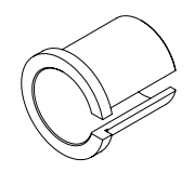
Brass Slip Sleeve
Ball Holder Plate MM002059-00
Ball Holder
Optional Components: o Extension Block o Suspension Plate
Upper Y axis and radius holder Installation {{if mft2 & nxy}}
Step-by-Step Installation
Remove the current adapter and holder if present
Every accessories must be removed along with the graphite plate.
The graphite plate will be mounted back in the next part.
Install the adapter plate
Position the rectangular plate along the Y axis of the load cell to support the module.
6-32 x .250” long using 7/64” Allen wrench
Install the Y axis module
Firstly, lose the tightening screw on the right to free the upper plate and have access to each screws.
Move the upper plate to 40mm and re tighten the side screw.
Secure the upper module with 4 x M4 x 8 screws using a 3mm metric Allen key.
Move back the plate to thighten the 2 last screws.
Install the graphite plate and the holder
Fix the adapter with four M4 x 12 screws using a 4mm metric Allen key.
Secure the graphite plate with four 6-32 x .250” screws long using 7/64” Allen wrench.
Tighten the two captive screws from the suspension using 9/64” Allen key.
Without suspension
Mount the graphite plate
Fix the holder with 4 x 10-32 x .438” using 5/32” Allen wrench
Center the holder to 0
50mm of total stroke length, considering 25mm is the center point.
⚠️
The side screws must be loosen first.
Adjust the micrometer screw to increase or decrease the Y offset manually.
Tighten the side screw.
Low Load Argon{{if ll}}
Low Load Argon : Ball holder and suspension installation
Secure the suspension holder with the 4 screws using 5/64” Allen Key.
The labeled force represents the suspension capability, not the nominal operating force.
The suspension must operate within this specified range. Exceeding this limit will lead to ineffective suspension operation.
Fix the suspension then secure it by tightening the side screw using 7/64” Allen key.
⚠️
Be careful not to overload the load cell while inserting the suspension.
You can install the suspension into the holder first before installing the holder on the load cell.
Or, as shown, you may insert a thin Allen key into the clamping gap during insertion to allow the part to slide in effortlessly.
Install or replace the ball from the ball holder, then hand-tighten the nut or using a wrench (optional).
Secure the ball holder once slide into the suspension by tightening the side screw using 3/32” Allen key.
⚠️
The ball holder must not touch the suspension base to ensure proper suspension operation.
It is possible to use a ball holder extension to reduce the Z distance to the sample in certain testing configurations.
Please contact Rtec Service for this specific matter.
Medium & High Load Argon{{if ml & hl}}
Pin/Ball holder Preparation {{if ball}}
Universal Ball holder Overview
Rtec balls catalog
Available Ball materials
E52100 Alloy Steel / HRC60
304 SSt / HRC25
440C SSt / HRC58
WC Tungsten Carbide / HRC75
SiN Silicon Nitride
Nonporous Alumina Ceramic balls
PTFE
Available Ball size
1.6mm
3.9mm
6.3mm
9.5mm
12.7mm
Rtec pins catalog
Available Pin materials
416 SSt
316 SSt
Titanium
Brass
PTFE
Peek
6061 Aluminum
Available Ball size
6.3mm
1. Test Ball or Pin
Provided for standard test: Ball, .250" (1/4") (6.350mm) Dia E52100 100Cr6 grade 25 Alloy Steel.
2. Nut
3. ER11 Collet
General metric range avalaible: from 1 mm to 7 mm (0.5 mm increments)
Each collet has a clamping range of 0.5 mm ex: an ER11-3 mm collet can also clamp pins/balls with a 2.5-3.5 mm diameter.
4. Adjusting pin
This pin enables ball position adjustment within the collet.
5. Ball Holder
Holder Specification
Rtec Part Number: AM000013-01
Collet Series
ER11
Shank Diameter
0.625 in / 15.875 mm
Minimum Collet Capacity
0.0190 in / 0.4826 mm
Maximum Collet Capacity
0.2760 in / 7.0104 mm
Overall Length
3.5 in / 76.2 mm
6. Extension
Left-Hand (reverse) threaded extension.
For additional information or to place an order, please contact Rtec Support (contact information provided at the end of this manual).
Loosen the nut to free the ball.
Remove the adjusting pin from the holder
{{! corr}}
Insert the adjusting pin into the holder, then the ball. Provided for standard test: Ball, .250" (1/4") (6.350mm) Dia E52100 100Cr6 grade 25 Alloy Steel.
Hold the holder vertically, so the ball is resting on the pin. Using a 1/8" Allen key, fasten the screw inside the holder to slightly push the ball.
Once the ball is retracted enough, fasten the nut to secure it.
{{if elec}}
Connect the ring/fork terminal to the brass collar using BHSCS 6-32 X .250” screws and a 7/64" allen key.
Connect the banana cable to the banana plug of the instrument:
Electrical Resistance Measurement (Keithley):
2-Wire measurement
Connect one cable from the collar to the “Force HI” connector.
4-Wire measruement
Connect one cable from the collar to the “Force HI” connector and one cable to “Sense HI”.
Place the collar on the ball holder and strongly tighten the 2 set screws on the side to secure the collet onto the ball holder.
{{If corr}}
Slide the ball holder shaft into the universal ball holder clamp and tighten the nut of the universal ball holder.
For preliminary testing: The ball may be reused by rotating it to expose a unworn contact surface. For final measurements: It is replace the ball between each test.
{{! dry&corr}}
Install the extension on the holder by rotating it counter-clockwise.
Increasing the ball holder length can negatively affect test results (longer force momentum), especially in reciprocating tests. It should only be used when using a chamber
⚠️
This extension uses a left-hand (reverse) thread:
To tighten: rotate counter-clockwise
To loosen: rotate clockwise
Place the collet on the ball holder and strongly tighten the 2 set screws on the side to secure the collet onto the ball holder.
Connect the banana cable to the banana plug of the instrument:
Electrical Resistance Measurement (Keithley):
2-Wire measurement
Connect one cable from the collar to the “Force HI” connector.
4-Wire measruement
Connect one cable from the collar to the “Force HI” connector and one cable to “Sense HI”.
Connect the ring/fork terminal to the brass collar using:
Firstly ,loosen the 2 tightening screws using /16” Allen key.
Slide in the block sample into the block support
Level the block sufficiently into the holder.
Tighten the securing screws on each side.
The self-leveling block holder will ensure proper contact during the test.
Block sample Quotation
Rtec Test Block Size: 0.620 x 0.250 x 0.4
L x l x h in inches
Reference : MM000128-XX
Dimension in inches
Place the collet on the ball holder and strongly tighten the 2 set screws on the side to secure the collet onto the ball holder.
Connect the banana cable to the banana plug of the instrument:
Electrical Resistance Measurement (Keithley):
2-Wire measurement
Connect one cable from the collar to the “Force HI” connector.
4-Wire measruement
Connect one cable from the collar to the “Force HI” connector and one cable to “Sense HI”.
Connect the ring/fork terminal to the brass collar using
BHSCS 6-32 X .250” screws and a 7/64" allen key.
{{if ml}}
BHSCS 4-40 X .125" screws and a 7/64" Allen key
{{if ll}}
{{if ev}}
Holder Installation
You can either mount the ball holder directly to the load cell or to a suspension which is used to limit the vibration induced by the sample during testing.
A test without suspension will be more noisy but will have a direct transfer of the forces to the load cell.
With a suspension
It is recommended to select a suspension system with the closest higher load rating to the expected load.
Example
For a test at 30N, you would need to use the 50N suspension. By doing so, you will mitigate the vibrations the most.
If you work at 48N it would be better to use a 100N suspension as the 50N suspension would not work for vibrations above 2N.
The labeled force represents the suspension capability, not the nominal operating force. The suspension must be used within this specified range and exceeding this limit will lead to ineffective suspension operation.
Mount the suspension on the graphite plate by tightening the 2 captive screws using 9/64” Allen key.
The label of the suspension should face the same direction as the load cell sticker.
Place the DELRIN disk {{if block&elec}}
Use four 1/4” button head screws to secure the mounting clamp to the load cell suspension and tighten using a 5/32” Allen wrench.
Slide the collet through the clamp {{if ball}}
Without a suspension
Place the DELRIN disk {{! block&elec}}
Use four 1/4” button head screws to secure the assembly to the load cell and tighten using a 5/32” Allen wrench.
Slide the collet through the clamp {{if ball}}
{{! block}}
Insert the slit sleeve into the mounting clamp.
PEEK or Brass slit sleeve, as mentioned in Required tools and components.
Place the ball holder into the slip sleeve.
⚠️
It is recommended to install the holder as far as possible into the suspension while making sure that it does not hit the load cell when the suspension is fully compressed.
{{! ball}}
Align the block holder key with the mounting clamp hole.
Place the block holder into the mounting clamp.
⚠️
It is recommended to install the holder as far as possible into the suspension while making sure that it does not hit the load cell when the suspension is fully compressed.
Tighten the mounting clamp using a 9/64” Allen wrench.
Montage with suspension
Montage without suspension
Scratch & Indentation Head preparation {{if head, table}}
Install the indenter inside the holder
If the Acoustic Emission sensor is not installed
If the capacitance sensor is not installed:
{{if table}}
Fz Installation {{if mft5 & Fz}}
Mounting the Fz Load Cell
Quick-exchange attachement
Sliding plate
Block extension
Fz load cell
Ensure that the quick-exchange plate is properly mounted on top of the load cell:
Mount the fz load cell on the fast exchange plate and tighten the 4 captive screws. (4 x 10-32 x 1.250” long using 5/32 Allen wrench).
Incorrect
The fast exchange plate’s notch should be pointing on the opposite side of the front load cell as this notch will fit into the back of the sliding support.
The front of the load cell is the face showing the Rtec logo and the unit calibration sticker.
(Optional) With Extension blocks:
You can also use an extension block to reduce the distance between the load cell and the lower setup.
2" (left) and 4" extensions (right)
Mount the block extension on the exchange plate with 4 4 x 10-32 x 1.250” long screws using 5/32 Allen wrench.
Install the load cell mounted on the extension block with the 4 captives screws. (4 x 10-32 x 1.250” long using 5/32 Allen wrench).
The fast exchange plate’s notch should be pointing on the opposite side of the front load cell as this notch will fit into the back of the sliding support.
The component at the top of the picture is the fast exchange adapter.
The front of the load cell is the face showing the Rtec logo and the unit calibration sticker.
Incorrect
Install the Fz load Cell
Lower the Z-Axis all the way down using the jogbox Z-axis control.
Slide the FZ-1D arm into the quick-exchange mount.
Secure the arm by locking it in place.
⚠️
Always power off the instrument before connecting or installing any load cell or accessory.
Connect the Sensor Cable.
Fx Installation {{if gauge, piezo}}
Arm montage (if dismounted)
The Fx sensor should come pre-built. However, if you need to build it, follow the following steps:
Firstly, attach the horizontal arm to the vertical arm. Screw the shoulder screw from the bottom hole with FHSHS 6-32 x .750” BM310271-08
There are 2 types of horizontal arms. The longer version is mostly used with environmental chambers. You need to select the arm depending on how long you want the ball holder to be.
Fix the capacitive sensor to the vertical arm with 2 x 8-32 x .875” BM310290-11.
The sensor face with the threaded insert.
Attach the friction arm to the pivot base with 8-32 x .375” BM310280-05 with a 9/64 » allen key.
{{if gauge}}
Fix the piezo sensor to the vertical arm with 2 x 8-32 x .875” BM310290-11.
{{if piezo}}
⚠️
Please refer to the 3 threads of the base which must point downward to ensure proper angular movement of the pivot base.
Mount the Fx-1D Arm
Remove the right panel of the MFT to access to the fixation hole and sticker
Position yourself at the right frame of the MFT and place the back of the arm (the pivot base)against the frame, making sure the base of the arm is pressed against it.
Refer to the alignment guide on the side of the instrument to determine the correct mounting holes.
The level of the friction arm depends on the configuration.
ex: For the block-on-ring configuration without heating chamber, use positions 5 and 7.
Attach the friction arm to the instrument using the 1.125-inch screws and washers to secure the arm. (1/4-20 x 1.000” BM310340-09). Hand-tighten initially; fully tighten with the 3/16” Allen Key after final adjustments.
Mount the pulling springs
Use a 5/64" Allen wrench to mount the springs to the front and back of the Fx-1D arm.
Ensure proper tension and secure the spring assembly.
Attach the Load Cell Cables
Connect the Fx Arm Cable to the Fz Load Cell.
{{gauge}}
Connect the piezo DB9 cable to the frame connector.
{{piezo}}
Raise the Z axis
Pin/Ball holder Preparation {{if ball AND Fz OR gauge OR piezo}}
Universal Ball holder Overview
Rtec balls catalog
Available Ball materials
E52100 Alloy Steel / HRC60
304 SSt / HRC25
440C SSt / HRC58
WC Tungsten Carbide / HRC75
SiN Silicon Nitride
Nonporous Alumina Ceramic balls
PTFE
Available Ball size
1.6mm
3.9mm
6.3mm
9.5mm
12.7mm
Rtec pins catalog
Available Pin materials
416 SSt
316 SSt
Titanium
Brass
PTFE
Peek
6061 Aluminum
Available Ball size
6.3mm
1. Test Ball or Pin
Provided for standard test: Ball, .250" (1/4") (6.350mm) Dia E52100 100Cr6 grade 25 Alloy Steel.
2. Nut
3. ER11 Collet
General metric range avalaible: from 1 mm to 7 mm (0.5 mm increments)
Each collet has a clamping range of 0.5 mm ex: an ER11-3 mm collet can also clamp pins/balls with a 2.5-3.5 mm diameter.
4. Adjusting pin
This pin enables ball position adjustment within the collet.
5. Ball Holder
Holder Specification
Rtec Part Number: AM000013-01
Collet Series
ER11
Shank Diameter
0.625 in / 15.875 mm
Minimum Collet Capacity
0.0190 in / 0.4826 mm
Maximum Collet Capacity
0.2760 in / 7.0104 mm
Overall Length
3.5 in / 76.2 mm
6. Extension
Left-Hand (reverse) threaded extension.
For additional information or to place an order, please contact Rtec Support (contact information provided at the end of this manual).
Loosen the nut to free the ball.
Remove the adjusting pin from the holder
{{! corr}}
Insert the adjusting pin into the holder, then the ball. Provided for standard test: Ball, .250" (1/4") (6.350mm) Dia E52100 100Cr6 grade 25 Alloy Steel.
Hold the holder vertically, so the ball is resting on the pin. Using a 1/8" Allen key, fasten the screw inside the holder to slightly push the ball.
Once the ball is retracted enough, fasten the nut to secure it.
{{if elec}}
Connect the ring/fork terminal to the brass collar using BHSCS 6-32 X .250” screws and a 7/64" allen key.
Connect the banana cable to the banana plug of the instrument:
Electrical Resistance Measurement (Keithley):
2-Wire measurement
Connect one cable from the collar to the “Force HI” connector.
4-Wire measruement
Connect one cable from the collar to the “Force HI” connector and one cable to “Sense HI”.
Place the collar on the ball holder and strongly tighten the 2 set screws on the side to secure the collet onto the ball holder.
{{If corr}}
Slide the ball holder shaft into the universal ball holder clamp and tighten the nut of the universal ball holder.
For preliminary testing: The ball may be reused by rotating it to expose a unworn contact surface. For final measurements: It is replace the ball between each test.
{{! dry&corr}}
Install the extension on the holder by rotating it counter-clockwise.
Increasing the ball holder length can negatively affect test results (longer force momentum), especially in reciprocating tests. It should only be used when using a chamber
⚠️
This extension uses a left-hand (reverse) thread:
To tighten: rotate counter-clockwise
To loosen: rotate clockwise
Place the collet on the ball holder and strongly tighten the 2 set screws on the side to secure the collet onto the ball holder.
Connect the banana cable to the banana plug of the instrument:
Electrical Resistance Measurement (Keithley):
2-Wire measurement
Connect one cable from the collar to the “Force HI” connector.
4-Wire measruement
Connect one cable from the collar to the “Force HI” connector and one cable to “Sense HI”.
Connect the ring/fork terminal to the brass collar using:
BHSCS 6-32 X .250” screws and a 7/64" allen key.
{{if ml}}
BHSCS 4-40 X .125" screws and a 7/64" Allen key
{{if ll}}
{{if ev}}
Ball holder Spring Setup {{if ball}}
Sleeve, insulator cap and the adaptor are placed on the top of the holder.
in order to be used with the suspensions.
For more information
A suspension is used to limit the vibration induced by the sample during testing. There are several variations of suspensions depending on the maximum load it can be effective on. .
It is recommended to select a suspension system with the closest higher load rating to the expected load. For example, if you realize a test at 150N, you would need to use the 200N suspension. By doing so, you will mitigate the vibrations the most.
Firstly ,loosen the 2 tightening screws using /16” Allen key.
Slide in the block sample into the block support
Level the block sufficiently into the holder.
Tighten the securing screws on each side.
The self-leveling block holder will ensure proper contact during the test.
Block sample Quotation
Rtec Test Block Size: 0.620 x 0.250 x 0.4
L x l x h in inches
Reference : MM000128-XX
Dimension in inches
Place the collet on the ball holder and strongly tighten the 2 set screws on the side to secure the collet onto the ball holder.
Connect the banana cable to the banana plug of the instrument:
Electrical Resistance Measurement (Keithley):
2-Wire measurement
Connect one cable from the collar to the “Force HI” connector.
4-Wire measruement
Connect one cable from the collar to the “Force HI” connector and one cable to “Sense HI”.
Connect the ring/fork terminal to the brass collar using
BHSCS 6-32 X .250” screws and a 7/64" allen key.
{{if ml}}
BHSCS 4-40 X .125" screws and a 7/64" Allen key
{{if ll}}
{{if ev}}
Block holder Spring Setup {{if ball}}
Sleeve, insulator cap and the adaptor are placed on the top of the holder.
in order to be used with the suspensions.
Slide in the block holder adapter sleeve.
Add the first cap to the top of the ball holder.
Place the spring onto the cap.
Add the top cap on top of the spring.
The pictures below show the actual montage step directly on the arm.
Follow the next step to continue
{{if Fz, gauge, piezo}}
Installing the montage into the arm
Unscrew the thumb screw/knob present on the front of the arm You can now open the securing block and insert the holder.
Insert the holer onto the arm and align the slot on the sleeve with the alignment pin on the arm.
The flange of the insulator sleeve must be positioned towards the top of the block holder For the block holder: Make sure that the notch matches the extrusion of the block holder
Slide the sleeve into position and loosely secure it.
Level the arm
Use the built-in level on the 1D arm to ensure the arm is mounted horizontally.
Manually press the arm so the ball holder contacts the sample, as the level must be evaluated when the pin/ball is in contact with the surface.
Slightly loosen the tightening screw/knob.
Adjust the arm position up or down until the level indicator shows proper alignment.
Once the 1D arm and block holder aligned and level, tighten the sleeve securely.
⚠️
The collets must be fully inserted into the arm
The ball holder and arm can remain suspended
{{if Fz, gauge, piezo}}
Fast-Exchange Installation
Mounting it with Extension
You can use an extension block to reduce the distance between the load cell and the lower setup.
2" (left) and 4" extensions (right)
Mount the block extension on the exchange plate with 4 4 x 10-32 x 1.250” long screws using 5/32 Allen wrench.
Then the adaptor plate mounted on the extension block with 4 x 10-32 x .625” long screws using 5/32 Allen wrench.
Install the load cell on the fast-exchange attachment by fastening the 4 captive screws using a 5/32" Allen wrench.
The narrow side of the fast exchange plate’s should point to the left of the front load cell as this side will fit into the back of the sliding support.
The front of the load cell is the face showing the Rtec logo and the unit calibration sticker.
{{if mft2&dry}}
Without Extension
Install the load cell on the fast-exchange attachment by fastening the 4 captive screws using a 5/32" Allen wrench.
The narrow side of the fast exchange plate’s should point to the left of the front load cell as this side will fit into the back of the sliding support.
The front of the load cell is the face showing the Rtec logo and the unit calibration sticker.
{{if mft2&!dry}}
Mounting it with Extension
(Optional) You can also use an extension block to reduce the distance between the load cell and the lower setup.
2" (left) and 4" extensions (right)
Without extension block (left) and with extension block (right)
Mount the block extension on the exchange plate with 4 4 x 10-32 x 1.250” long screws using 5/32 Allen wrench.
Then the adaptor plate mounted on the extension block with 4 x 10-32 x .625” long screws using 5/32 Allen wrench.
{{if mft5&dry}}
Without Extension
In most cases, the Argon adapter plate will already be installed. However, if installation is required, follow these steps:
Mount the adaptor plate plate directly to the Quick Exchange base using the provided 4 x 10-32 x 1.250” long screws using 5/32” Allen wrench.
Install the load cell on the fast-exchange attachment by fastening the 4 captive screws using a 5/32" Allen wrench.
Align the sensor so that the ribbon cable port is on the right-hand side when viewed from the front.
This ensures correct orientation in relation to the rear alignment features of the Quick Exchange.
{{if mft5&!dry}}
Installing the Load Cell
Sliding It into the Tester
Slide in the load cell into the Z stage rack.
Make sure the 4 screws above the rack are removed. Slide the load cell with its front facing you and the connector on the right.
Fasten the 4 securing screws by hands.
Connect the ribbon cable. The connector only fit one way.
{{if mft2}}
Manually adjust the Y Radius
To adjust the y radius you need to manually turn the knob to the desired radius.
The center of the Y radius setup being the 25mm mark, you can adjust the radius to +-25mm.
{{if mft2&nxy}}
Sliding It into the Tester
Lower the Z-Axis all the way down using the jogbox.
To create clearance, move the Y-stage.
Before installing the load cell
Lower the Z-Axis all the way down using the jogbox, to have access to the attachement.
Ensure the Y-stage is moved sufficiently backward to avoid obstruction. Although unlikely to cause damage, improper placement may interfere with installation.
Animated instructions
Slide the sensor assembly with the Quick Exchange into the MFT-5000 Quick Exchange Dock
Ensure first that the locking wings are forward.
The front of the load cell (Rtec logo and sticker) is facing you.
Lift the Argon Assembly up while tightening the Quick Exchange locks outward
Always hold the sensor by its sides to avoid applying force on the sensors.
Make sure the assembly is firmly wedged up with no vertical play.
Connect the ribbon cable to the Argon Load Sensor.


(6).gif)

(4).gif)
(5).gif)

.gif)
.gif)
.gif)
.gif)
.gif)
.gif)
(1)_(1).gif)


(1).gif)
 Made with Bullet